Circuit Diagram Feedback Nand
Nand cmos gate input output students Gate timing nand logic Schematic nand input logic physical righto
How to draw 2 input NAND gate layout in Microwind - YouTube
Nand flop S-r flip flop using nand gate Nand stick diagram
Hierarchical virtuoso lab5
Solved draw the stick diagram for a full adder. (in color).Nand diode Reverse-engineering the standard-cell logic inside a vintage ibm chipSolved a nand gate has been added as a feedback path for the.
Logic gate timing diagram 1 and gate timingGate stick diagram nand layout cmos aoi flip flop adder full triggered edge invert draw example vp latch implemented transcribed How to draw 2 input nand gate layout in microwindNand gate layout input draw lw.

Cmos 2 input nand gate
Ece429 lab5☑ diode resistor logic nand gate Been has shift register feedback nand gate path added solvedNand stick gate diagram vlsi cmos input mos logic circuit schematic two transistors figure euler pun accessed same again being.
.


CMOS 2 input NAND gate | All For Students
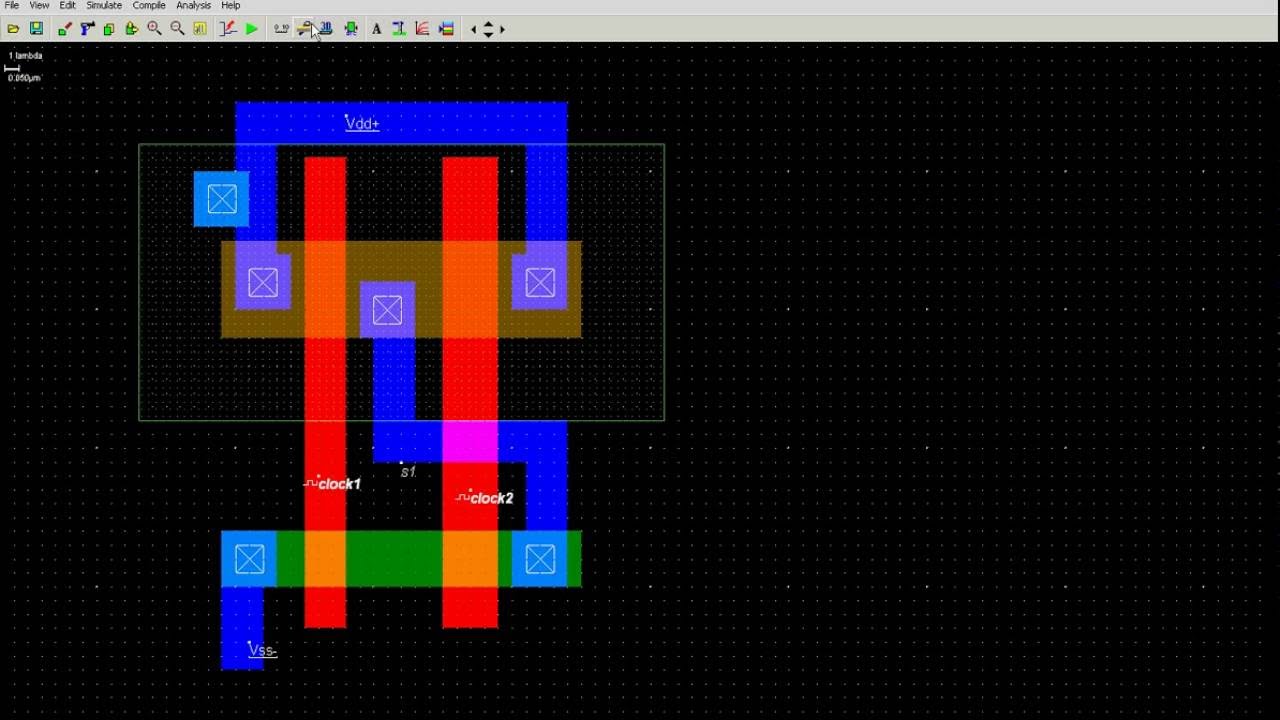
How to draw 2 input NAND gate layout in Microwind - YouTube

Reverse-engineering the standard-cell logic inside a vintage IBM chip

Solved Draw the stick diagram for a Full Adder. (in color). | Chegg.com

Nand Stick Diagram - Wiring Diagram Pictures

Solved A NAND gate has been added as a feedback path for the | Chegg.com

☑ Diode Resistor Logic Nand Gate

LOGIC GATE TIMING DIAGRAM 1 And gate timing